As we all know, portable medical electronics has been greatly developed and widely used in recent years. More and more new products are already on the market. The products that are effective and can be mass-produced are those that are simple in design and superior in performance, so as to reduce the cost of equipment. To do this, designers need to consider power consumption, cost, size, FDA certification of the device, and other factors.
A typical portable medical electronic system consists of the following parts: analog front end (for data acquisition), amplifiers and filters (for signal conditioning), analog to digital converters and sensors (for signal acquisition), buttons (for Accept user feedback), microcontroller (execution algorithm), and a variety of interfaces, such as LCD monitors, USB ports, and more. Traditional design requires all the required components to be placed on the PCB. This approach increases the BOM, PCB complexity, and design cycle of the entire system. The use of discrete devices is also not conducive to IP protection because it can be easily copied.
The design and production of portable medical devices is also regulated by the Food and Drug Administration (FDA). This means that their design and production must follow an accurate process archive, performance must meet the documentation requirements, and must pass development testing, mass production testing and field applications. A national food and drug administration requires that devices used in medical devices be available for the next five years. This spurs developers to reduce the overall device count for easier FDA certification.
Figure 1 Traditional design of blood pressure monitor
Figures 1 and 2 show a typical blood pressure monitor (BPM) and a non-contact digital thermometer using a traditionally designed solution architecture.
Figure 2 Traditional design of non-contact digital thermometer
Traditional scheme
A typical blood pressure monitor uses a differential pressure sensor to measure the pressure in the cuff or arm. This sensor is used as an output, only a few tens of microvolts (30μV ~ 50μV), the output pressure signal needs to be amplified with a high gain amplifier to achieve a good common mode rejection ratio (CMRR). Typically the gain and common mode rejection ratios need to be approximately 150 and 100 decibels, respectively. The pulse signal of the pressure signal has a frequency between 0.3 Hz and 11 Hz and an amplitude of about several hundred microvolts. This type of oscillation can be extracted by a bandpass filter with a gain of 200 and a cutoff frequency of 0.3 Hz to 11 Hz. A 10-bit ADC with a speed of 50 Hz is used to digitize the pressure sensor and vibration signal. Two timers are used to calculate the heartbeat and implement a safety timer. The safety timer is used to adjust the pressure to remain in the target arm for a certain period of time. The security timer is part of the security rules in the AAMI standard. A microcontroller core uses various algorithms to calculate its systolic and diastolic pressure values. The PWM motor is driven to expand and contract the cuff.
A typical non-contact digital thermometer uses a sensor (or thermocouple thermocouple) that consists of a thermocouple (used to measure the thermocouple temperature) and a thermistor (used to measure the ambient temperature). film. The thermocouple generates a DC voltage based on the voltage difference between the nodes. The output of the thermocouple is kept at a few microvolts. The thermocouple signal is amplified by a low noise precision amplifier. A voltage divider is formed by a thermistor and an external precision voltage regulator. This voltage divider is used to convert the change in the thermistor voltage to temperature. The voltages of the thermocouple and the thermistor are used to calculate the thermocouple and ambient temperature. The voltage is obtained by a formula given by the sensor manufacturer or a pre-stored look-up table to obtain the temperature. The ambient temperature plus the thermocouple temperature is the final temperature measurement.
Of course, in the above applications, other peripheral circuits such as field LCD driver, real time clock RTC, button, EEPROM and USB are also required.
Industrial 100Hz LiDAR Solutions
Industrial Laser Distance Sensor of the IT02S & IT03M series are designed for measurements of moving targets. The LiDAR distance sensor is a ToF (Time of Flight) LiDAR sensor capable of measuring the distance to an object as close as 3 centimeters and as far as 15 meters! The LiDAR laser sensor is widely used in many innovative applications on the market, including smart dustbin, unmanned supermarket etc.long distance control system.
Application areas of the sensor are:
> Harsh environments, like outdoors in strong sunlight
> Black surface can be up to 8m
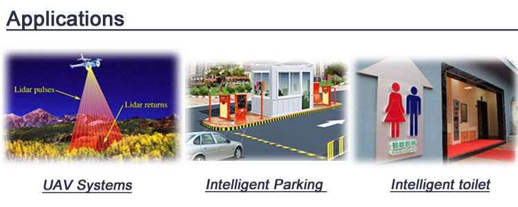
> UAV/Drone Systems
> Intelligent Parking
> Smart Measure Systems
> Intelligent toilet

Industrial Lidar Sensor,Tof Laser Measurement Module,Tof Sensors,Time Of Flight Distance Sensor
Chengdu JRT Meter Technology Co., Ltd , https://www.rangingsensor.com